| Vacuum-Driven Attitude Indicators.
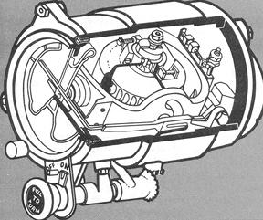
The cut-away diagram in Figure 4-21 shows the basic components of a typical older type attitude indicator. These instruments are still in common use in general aviation aircraft. Figure 4-21. Attitude indicator components (vacuum-driven).
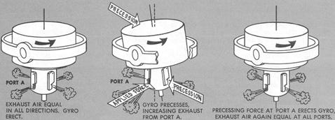
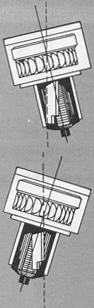
The rotor, mounted in a sealed housing, spins in a horizontal plane about the vertical axis. The housing pivots about the lateral axis on a gimbal, which in turn is free to pivot about the longitudinal axis. The instrument case is the third gimbal necessary for universal mounting. The horizon bar is linked to the gyro by a lever, attached to a pivot on the rear of the gimbal frame and connected to the gyro housing by a guide pin. When the attitude indicator is in operation, gyroscopic rigidity maintains the horizon bar parallel to the natural horizon. When the pitch or bank attitude of the aircraft changes, the miniature aircraft, being fixed to the case, moves with it. These movements of the instrument case with respect to the gyro are shown on the face of the instrument as pitch and bank attitude changes of the miniature aircraft with respect to the horizon bar. Air is sucked through the filter, then through passages in the rear pivot and inner gimbal ring, then into the housing, where it is directed against the rotor vanes through two openings on opposite sides of the rotor. The air then passes through four equally spaced ports in the lower part of the rotor housing and is sucked out into the vacuum pump or venturi tube. The chamber containing the ports is the erecting device that returns the spin axis to its vertical alignment whenever a precessing force, such as friction, displaces the rotor from its horizontal plane. The four exhaust ports are each half-covered by a pendulous vane, which allows discharge of equal volumes of air through each port when the rotor is properly erected. Any tilting of the rotor disturbs the total balance of the pendulous vanes, tending to close one vane of an opposite pair while the opposite vane opens a corresponding amount. The increase in air volume through the opening port exerts a precessing force on the rotor housing to erect the gyro, and the pendulous vanes return to a balanced condition. See Figures 4-22 and 4-23. Limits. The limits of the instrument refer to the maximum rotation of the gimbals beyond which the gyro will tumble. The older type vacuum-driven attitude indicators have bank limits of approximately 100° to 110°, and pitch limits of 60° to 70°. If, for example, the pitch limits are 60° with the gyro normally erected, the rotor will tumble when the aircraft climb or dive angle exceeds 60°. As the rotor gimbal hits the stops, the rotor precesses abruptly, causing excessive friction and wear on the gimbals. The rotor will normally precess back to the horizontal plane at a rate of approximately 8° per minute. The limits of more recently developed vacuum-driven attitude indicators exceed those given above. Figure 4-22. Erecting mechanism, vacuum-driven attitude indicator.
Figure 4-23. Action of Pendulous vanes.
Caging. Many gyros include a manual caging device, used to erect the rotor to its normal operating position prior to flight or after tumbling, and a flag to indicate that the gyro must be uncaged before use. Turning the caging knob prevents rotation of the gimbals and locks the rotor spin axis in its vertical position. Because the rotor is spinning as long as vacuum power is supplied, normal maneuvering with the gyro caged wears the bearings unnecessarily. Therefore, the instrument should be left uncaged in flight unless the limits are to be exceeded. In the caged position, the gyro is locked with the miniature aircraft showing level flight, regardless of aircraft attitude. When uncaged in flight, in any attitude other than level flight, the gyro will tend to remain in an unlevel plane of rotation with the erecting mechanism attempting to restore the rotor to a horizontal plane. Therefore, should it be necessary to uncage the gyro in flight, the actual aircraft attitude must be identical to the caged attitude (that is, straight and level), otherwise, the instrument will show false indications when first uncaged. Errors. Errors in the indications presented on the attitude indicator will
result from any factor that prevents the vacuum system from operating within the
design suction limits, or from any force that disturbs the free rotation of the
gyro at design speed. Some errors are attributable to manufacturing and
maintenance. These include poorly balanced components, clogged filters,
improperly adjusted valves, and pump malfunction. Such errors can be minimized
by proper installation and inspection. Errors in both pitch and bank indications occur during normal coordinated turns. These errors are caused by the movement of the pendulous vanes by centrifugal force, resulting in the precession of the gyro toward the inside of the turn. The error is greatest in a 180° steep turn. If, for example, a 180° steep turn is made to the right and the aircraft is rolled out to straight-and-level flight by visual references, the miniature aircraft will show a slight climb and turn to the left. This precession error, normally 3° to 5°, is quickly corrected by the erecting mechanism. At the end of a 360° turn, the precession induced during the first 180° is canceled out by precession in the opposite direction during the second 180° of turn. The slight precession errors induced during the roll-out are corrected immediately by pendulous vane action. Acceleration and deceleration also induce precession errors, depending upon the amount and extent of the force applied. During acceleration the horizon bar moves down, indicating a climb. Control applied to correct this indication will result in a pitch attitude lower than the instrument shows. The opposite error results from deceleration. Other errors, such as "transport precession" and "apparent precession," relate to rotation of the earth and are of importance to pilots and navigators concerned with high speed and long-range flight. The application of the foregoing errors as they affect instrument interpretation will be treated later in Chapter V, "Attitude Instrument Flying - Airplanes." Electric Attitude Indicators. In the past, suction-driven gyros have been favored over the electric for light aircraft because of the comparative simplicity and lower cost. However, the increasing importance of the attitude indicator has stimulated development of improved electric-driven gyros suited to light plane installation. Improvements relating to basic gyro design factors, easier readability, erection characteristics, reduction of induced errors, and instrument limitations are reflected in several available types. Depending upon the particular design improvements, the details among different instruments will vary as to the instrument display and cockpit controls. All of them present, to a varying degree, the essential pitch and bank information for attitude reference. Electric gyros may be remotely located, with the gyro assembly mounted
at some convenient location other than behind the instrument panel, and with the
indicator assembly on the instrument panel driven through a servo motor. Another
type is a simpler unit incorporating the gyroscope motor in the instrument case
integral with the indicator assembly. The H-6B attitude indicator and J-8
gyro-horizon are representative of this type (Figs. 4-24 and 4-25).
|