| DEAD RECKONING
Dead reckoning is navigation solely by means of computations based on
time, airspeed, distance, and direction. The products derived from these
variables, when adjusted by windspeed and velocity, are heading and groundspeed.
The predicted heading will guide the airplane along the intended path and the
groundspeed will establish the time to arrive at each checkpoint and the
destination. The word “dead” in dead reckoning is actually derived from “ded,”
or deduced reckoning. Except for flights over water, dead reckoning is usually
used with pilotage for cross-country flying. The heading and groundspeed as
calculated is constantly monitored and corrected by pilotage as observed from
checkpoints.
The Wind Triangle or Vector Analysis
If there is no wind, the airplane’s ground track will be the same as
the heading and the groundspeed will be the same as the true airspeed. Only on
rare occasions does this condition exist. A wind triangle, the pilot’s version
of vector analysis, is the backbone of dead reckoning.
The wind triangle is a graphic explanation of the effect of wind upon
flight. Groundspeed, heading, and time for any flight can be determined by using
the wind triangle. It can be applied to the simplest kind of cross-country
flight as well as the most complicated instrument flight. The experienced pilot
becomes so familiar with the fundamental principles that estimates can be made
which are adequate for visual flight without actually drawing the diagrams.
| The beginning student, however, needs to develop skill in constructing
these diagrams as an aid to the complete understanding of wind effect.
Either consciously or unconsciously, every good pilot thinks of the flight
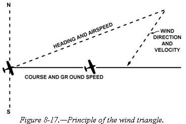
in terms of wind triangle. If a flight is to be made on a course to the
east, with a wind blowing from northeast, the airplane must be headed
somewhat to the north of east to counteract drift. This can be represented
by a diagram as shown in figure 8-17. Each line represents direction and
speed. The long dotted line shows the direction the plane is heading, and
its length represents the airspeed for 1 hour. The short dotted line at
the right shows the wind direction, and its length represents the wind
velocity for 1 hour. The solid line shows the direction of the track, or
the path of the airplane as measured over the Earth, and its length
represents the distance traveled in 1 hour, or the groundspeed. |
|
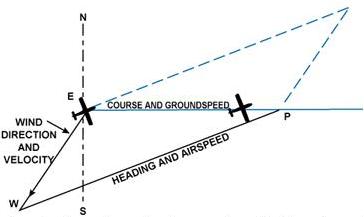
| In actual practice, the triangle illustrated in figure 8-17 is not
drawn; instead, construct a similar triangle as shown by the black lines
in figure 8-18, which is explained in the following example.
Suppose a flight is to be flown from E to P. Draw a line on the
aeronautical chart connecting these two points, measure its direction with
a protractor, or plotter, in reference to a meridian. This is the true
course which in this example is assumed to be 090° (east). From the
National Weather Service, it is learned that the wind at the altitude of
the intended flight is 40 knots from the northeast (045°). Since the
National Weather Service reports the windspeed in knots, if the true
airspeed of the airplane is 120 knots, there is no need to convert speeds
from knots to MPH or vice versa. |
|
|
Figure 8-18.—The wind triangle as is drawn in navigation practice.
Blue lines show the triangle as drawn in figure
8-17. |
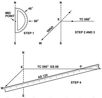 |
Now on a plain sheet of paper draw a vertical line representing north
and south. (The various steps are shown in figure 8-19.) Place the
protractor with the base resting on the vertical line and the curved edge
facing east. At the center point of the base, make a dot labeled “E”
(point of departure), and at the curved edge, make a dot at 90°
(indicating the direction of the true course) and another at 45°
(indicating wind direction).
With the ruler, draw the true course line from E, extending it
somewhat beyond the dot by 90°, and labeling it “TC 090°.”
Next,
align the ruler with E and the dot at 45°, and draw the wind arrow from E,
not toward 045°, but downwind in the direction the wind is blowing, making
it 40 units long, to correspond with the wind velocity of 40 knots.
Identify this line as the wind line by placing the letter “W” at the end
to show the wind direction. Finally, measure 120 units on the ruler to
represent the airspeed, making a dot on the ruler at this point. The units
used may be of any convenient scale or value (such as 1/4 inch = 10
knots), but once selected, the same scale must be used for each of the
linear movements involved. Then place the ruler so that the end is on the
arrowhead (W) and the 120 knot dot intercepts the true course line. Draw
the line and label it “AS 120.” The point “P” placed at the intersection,
represents the position of the airplane at the end of 1 hour. The diagram
is now complete. |
| Figure 8-19.—Steps in drawing the wind triangle. |
|
| The distance flown in 1 hour (groundspeed) is measured as
the numbers of units on the true course line (88 nautical miles per hour
or 88 knots).
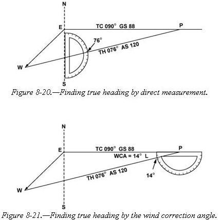
The true heading necessary to offset drift is indicated by the
direction of the airspeed line which can be determined in one of two ways:
• By placing the straight side of the protractor along the north-south
line, with its center point at the intersection of the airspeed line and
north-south line, read the true heading directly in degrees (076°).
[Figure 8-20]
• By placing the straight side of the protractor along
the true course line, with its center at P, read the angle between the
true course and the airspeed line. This is the wind correction angle (WCA)
which must be applied to the true course to obtain the true heading. If
the wind blows from the right of true course, the angle will be added; if
from the left, it will be subtracted. In the example given, the WCA is 14°
and the wind is from the left; therefore, subtract 14° from true course of
090°, making the true heading 076°. [Figure 8-21] |
|
After obtaining the true heading, apply the correction for magnetic variation
to obtain magnetic heading, and the correction for compass deviation to obtain a
compass heading. The compass heading can be used to fly to the destination by
dead reckoning.
To determine the time and fuel required for the
flight, first find the distance to destination by measuring the length of the
course line drawn on the aeronautical chart (using the appropriate scale at the
bottom of the chart). If the distance measures 220 NM, divide by the groundspeed
of 88 knots, which gives 2.5 hours or (2:30) as the time required. If fuel
consumption is 8 gallons an hour, 8 x 2.5 or about 20 gallons will be used.
Briefly summarized, the steps in obtaining flight information are as follows:
• TRUE COURSE—Direction of the line connecting two desired points, drawn on
the chart and measured clockwise in degrees from true north on the mid-meridian.
• WIND CORRECTION ANGLE—Determined from the wind triangle. (Added to TC if
the wind is from the right; subtract if wind is from the left.)
• TRUE
HEADING—The direction measured in degrees clockwise from true north, in which
the nose of the plane should point to make good the desired course.
•
VARIATION—Obtained from the isogonic line on the chart. (Added to TH if west;
subtract if east.)
• MAGNETIC HEADING—An intermediate step in the
conversion. (Obtained by applying variation to true heading.)
•
DEVIATION—Obtained from the deviation card on the airplane. (Added to MH or
subtracted from, as indicated.)
• COMPASS HEADING—The reading on the compass
(found by applying deviation to MH) which will be followed to make good the
desired course.
• TOTAL DISTANCE—Obtained by measuring the length of the TC
line on the chart (using the scale at the bottom of the chart).
•
GROUNDSPEED—Obtained by measuring the length of the TC line on the wind triangle
(using the scale employed for drawing the diagram).
• TIME FOR FLIGHT— Total
distance divided by groundspeed.
• FUEL RATE—Predetermined gallons per hour
used at cruising speed.
NOTE: Additional fuel for adequate reserve should be added as a safety
measure.
|